On-Off switch using 2 relays - Four versions
The load wired to output of such device is connected and disconnected by each momentarily
pressing on a pushbutton, the arrangement having a toggle flip-flop function, or toggle bistable.
The three versions are presented, based on the momentary pushbutton respectively single normally-open, SPDT and DPDT type.
If the arrangement needs a single normally-open contact, an important advantage results, consists in posibility of parallel wiring of several pushbuttons to make control available from multiple locations, so if this arrangement is use to supply a lighting circuit, this can be a viable solution to replace the special relays normally used in electrical wiring:
- Stepping Relay
- Latching Relay
- Impulse Relay
For example, a SPDT pushbutton we can use, a microswitch adapt to be activate by the finger.
SPDT - Single Pole Double Throw.
A common terminal (C) is connected to either of two other terminals:
NC (Normally Closed) and NO (Normally Open) are be used to designate terminals when the switch is in the off or deactivated state.

This is the same configuration as what is known as a '3-way' switch for electrical (house) wiring (Two of these are used to control a fixture from separate locations), but, as opposed to those, having momentary action.
SPDT - Single Pole Double Throw.
A common terminal (C) is connected to either of two other terminals:
NC (Normally Closed) and NO (Normally Open) are be used to designate terminals when the switch is in the off or deactivated state.
This is the same configuration as what is known as a '3-way' switch for electrical (house) wiring (Two of these are used to control a fixture from separate locations), but, as opposed to those, having momentary action.
Version 1
Using a normally open pushbutton
Using a normally open pushbutton


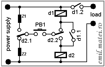
A very interesting, clever design, from an old book on relay circuit design, a toggle flip-flop, using two relays only , is shown:


Initial, the circuit is as shown in the above picture (STEP 4)
, both relays are de-energized.
When we press (push) button to START, (Figure - STEP 1) , relay d1 takes the fully supply voltage, ONLY DURING THE FINGER IS PUSHING THE BUTTON. Current flows through relay d1, contact d2.2, button PB1 and contact d2.1. During step 1, the coil of d2 is bypassed by d1.1+d2.2+PB1+d2.1; there is no path for current through relay d2, so relay d2 is not yet energized. Contact d1.2 turns on the supplied load.
When the pushbutton is released, to continue the starting process, Figure - STEP 2 , because relay d1 is energized and contact d1.1 is closed, the opening of the PB1 diverts current through the coil of relay d2 (now, d2 is not bypassed). Current flows through coil of relay d1, series coil of relay d2 and contact d1.1. This is the finnish of step 2, the flipflop will stay in this configuration indefinitely. This is a STABLE STATE OF THE FLIPFLOP, when the load is supplied.
Now, we want to turn off the load and we actuate the pushbutton again, by pressing it. Current flows like in Figure - STEP 3 , through the coil of relay d2. Relay d2 takes the fully supply voltage - ONLY WHEN THE FINGER IS PUSHING THE BUTTON. This is the step 3. Now, the coil of d1 is bypassed by d2.1+PB1+d2.2, there is no path for current through relay d1, so relay d1 is de-energized, contacts d1.1 and d1.2 now opens. The load supply is OFF.
There is not any reason to stay with the finger on the button PB1 anymore, the pushbutton is released, and current stops flowing through the coil of relay. We are back to the intitial configuration. This is the finnish of step 4. The flipflop will stay in this configuration indefinitely. This is the STABLE STATE OF THE FLIPFLOP, when the load is not powered (OFF).
The relays are either both energized or both de-energized. Because when both relays are energized, the coils are series connected, there is need to to choose relays having nominal voltage around half of the supply voltage.
The choice of the relays is based on HOLD current and PULL-in current.
This flipflop uses a feature of the relays:
THE HOLD CURRENT IS MUCH LESS THAN THE PULL-IN CURRENT
.
The hysteresis is exploited by this circuit.
Once a relay is energized, it can keep relay actuated even though
its coil is in serie with the coil of other relay.
The full supply voltage is applied to relays coils during pushing the PB1, when pushbutton is pressed to ON, or to OFF the circuit (step 1 and step 3). This is an intermediary state of the circuit, not permanently.
The half of supply voltage is applied on the coils of each relay in the stable state of the circuit, when the pushbutton is released and the circuit is in the ON state, and the flipflop stay in this configuration indefinitely.
During the intermediary state of the circuit, overvoltage is not dangerous for the life of the relays, if they are corecly choosen for the electric characteristics point of view.
To diminish the current through the relay coils during the button is pressed, we can insert additional immpedances, Z1, Z2, placed series NO and NC of d2.1.
 Z2 reduces rate of current flowing through d1 coil, during the fully supply
voltage is applied across it (step 1), Z1 reduces rate of current flowing through
d2 coil during the step 3.
Z2 reduces rate of current flowing through d1 coil, during the fully supply
voltage is applied across it (step 1), Z1 reduces rate of current flowing through
d2 coil during the step 3.
The full supply voltage is applied to relays coils during pushing the PB1, when pushbutton is pressed to ON, or to OFF the circuit (step 1 and step 3). This is an intermediary state of the circuit, not permanently.
The half of supply voltage is applied on the coils of each relay in the stable state of the circuit, when the pushbutton is released and the circuit is in the ON state, and the flipflop stay in this configuration indefinitely.
During the intermediary state of the circuit, overvoltage is not dangerous for the life of the relays, if they are corecly choosen for the electric characteristics point of view.
To diminish the current through the relay coils during the button is pressed, we can insert additional immpedances, Z1, Z2, placed series NO and NC of d2.1.
Z2 reduces rate of current flowing through d1 coil, during the fully supply
voltage is applied across it (step 1), Z1 reduces rate of current flowing through
d2 coil during the step 3.Version 2
Using a DPDT pushbutton
Using a DPDT pushbutton

Using a traditional relays, a very interesting Java applet from
University of Hamburg suggestivelly demonstrates how a toggle-flipflop built
from 3 relays works:
http://tams-www.informatik.uni-hamburg.de/applets/hades/webdemos/05-switched/20-relays/flipflop3.html
Refering to mentioned schematic, a little modification comes to an arrangement using two
relays only, if a DPDT momentary push button is used:

Version 3
Using a SPDT pushbutton
Using a SPDT pushbutton


Version 4
Using a SPDT pushbutton
Using a SPDT pushbutton

